


Abstract
It is thought that the stress concentration at the root apex caused by orthodontic force induces root resorption. The purpose of this study was to investigate stress distribution at the root in cases of deviated root shapes using finite element models (FEMs). To clarify this, five three-dimensional FEMs divided by deviated root shape (normal, short, blunt, bent root apex, pipette shape) were constructed and, experimental orthodontic forces, applied in a vertical (intrusive) and horizontal (lingual) direction to the tooth axis.
In the short-root model, significant stress was concentrated at the middle of the root. The blunt-shaped root model showed no significant stress concentration at the root. In the models with a bent or pipette-shaped root, significant stress was concentrated at the root apex. During orthodontic force application, stress concentration was observed in the root of the models with short, bent, and pipette-shaped roots, indicating that attention must be paid to root shape during orthodontic treatment.
Introduction
Apical root resorption is a biological response to an orthodontic force. Massler and Malone (1954) stated that root resorption occurs in 100 per cent of orthodontic patients. There are many reports regarding the relationship between orthodontic treatment and root resorption (Dermaut and De Munck, 1986; McFadden et al., 1989; Linge and Linge, 1991; Baumrind et al., 1996; Parker and Harris, 1998; Sameshima and Sinclair, 2001b; Chan et al., 2004; Chan and Darendeliler, 2005). Chan and Darendeliler (2005) stated that excessive orthodontic force might result in root resorption. Sameshima and Sinclair (2004), in a comparative study using radiographs taken before and after orthodontic treatment, reported that teeth with an abnormal root morphology frequently show external root resorption compared with teeth with a normal root shape. Mirabella and Årtun (1995) also considered that an abnormal root shape was a significant risk factor for root resorption. According to the deviated root shape, if orthodontic force is concentrated at a particular region of the apical root, then, root resorption may occur. However, no biomechanical studies have been published that clarify the influence of a deviated root shape on root resorption. It is clinically significant to understand the difference of stress distribution at the root apex according to the deviated root shape.
This study aimed to clarify the difference in stress distribution at the root apex due to a variation of root shape during orthodontic force application using finite element models (FEMs).
Materials and methods
Preparation for FEM
FEMs, including the upper central incisor, pulp, periodontal membrane, and alveolar bone (Figures 1 and 2), were constructed using a three-dimensional computer aided design program (SolidWorks2004, SolidWorks Japan K.K., Tokyo, Japan). Five models (Figure 3) were made based on the classification of root shape derived from Levander and Malmgren (1988). Model A was constructed with a normal root shape with a crown length of 10.5 mm and a root length of 13.0 mm based on the data derived from Ash (1984). Four other models (B, C, D, and E) with various root shapes were constructed. Model B had a short root length (8 mm), model C a blunt root apex, model D a distally bent root apex, while in model E the root was pipette shaped with constriction at the root apex. The periodontal membrane which surrounded the root surface was 200 μm thick. The alveolar bone was divided into cancellous and cortical bone, with the cancellous bone surrounded by the cortical bone with a thickness of 2.0 mm.
Finite element model of a maxillary central incisor in the alveolar bone.
Component materials of the finite element model.
The five models based on the classification of root shape derived from Levander and Malmgren (1988). (A) Normal, (B) short, (C) blunt, (D) bent, and (E) pipette shape at root apices.
Material properties
Each structure, central incisor, pulp, periodontal membrane, cancellous bone, and cortical bone, was meshed using an auto-meshing routine in the finite element (FE) analysis program (Cosmos/Works2004, Cosmos Japan Co., Tokyo, Japan). Table 1 shows the number of nodes and elements for each model. The material properties for all models were defined as linear (Middleton et al., 1996; Papavasiliou et al., 1996; Table 2).
Number of nodes and elements.
| Model | Number of nodes | Number of elements |
| A: Normal root | 76 782 | 53 659 |
| B: Short root | 73 501 | 51 189 |
| C: Blunt root | 71 990 | 50 059 |
| D: Bent root | 70 952 | 49 247 |
| E: Pipette-shaped | 76 597 | 53 514 |
| Model | Number of nodes | Number of elements |
| A: Normal root | 76 782 | 53 659 |
| B: Short root | 73 501 | 51 189 |
| C: Blunt root | 71 990 | 50 059 |
| D: Bent root | 70 952 | 49 247 |
| E: Pipette-shaped | 76 597 | 53 514 |
Material properties
| Young's modules (MPa) | Poisson's ratio | |
| Tooth (enamel) | 84 100 | 0.20 |
| Pulp | 2 | 0.45 |
| Periodontal ligament | 0.75 | 0.45 |
| Cancellous bone | 345 | 0.30 |
| Cortical bone | 13 800 | 0.26 |
| Young's modules (MPa) | Poisson's ratio | |
| Tooth (enamel) | 84 100 | 0.20 |
| Pulp | 2 | 0.45 |
| Periodontal ligament | 0.75 | 0.45 |
| Cancellous bone | 345 | 0.30 |
| Cortical bone | 13 800 | 0.26 |
Boundary conditions and solution
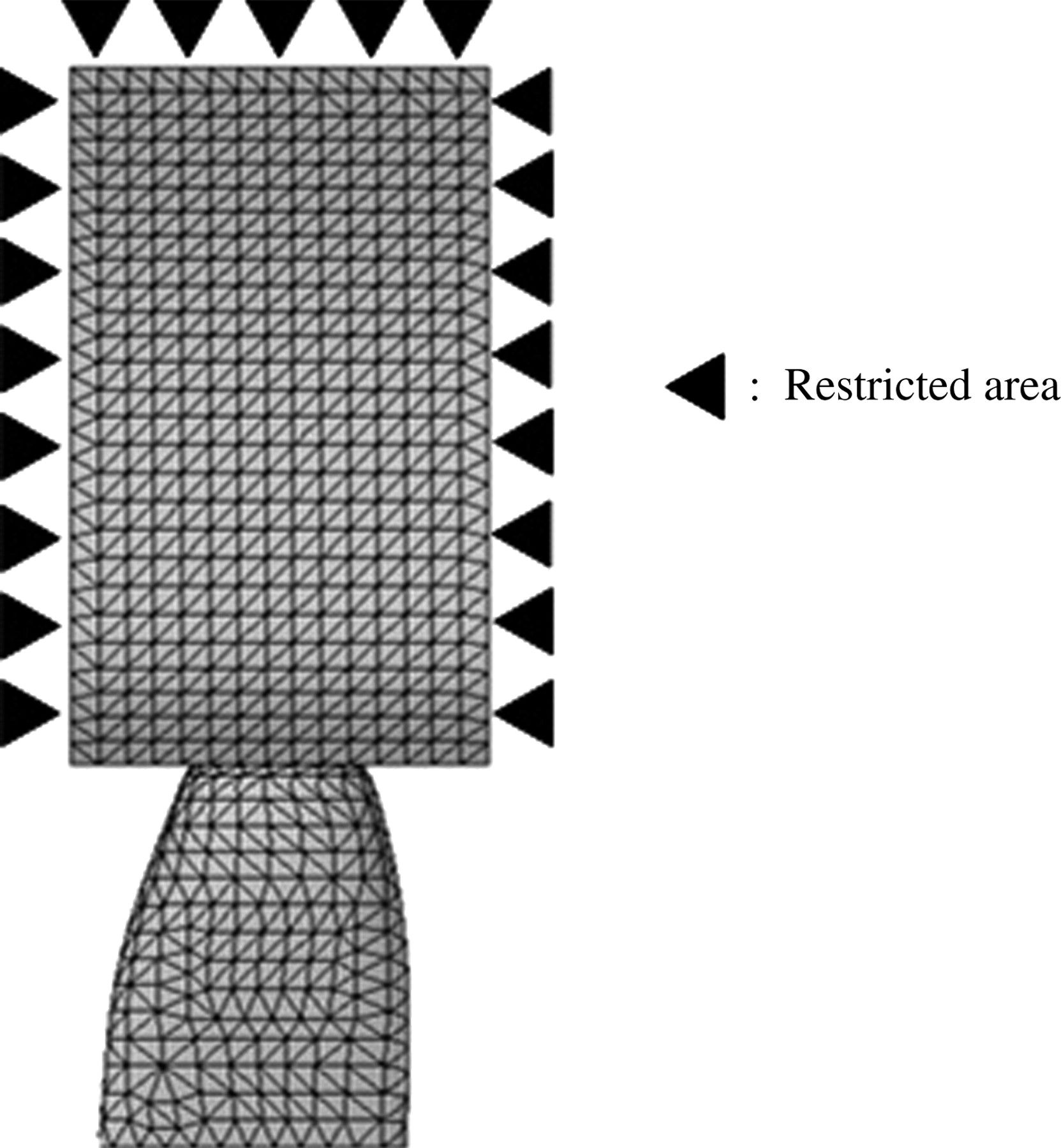
Nodes at the mesio-distal and the bottom surface of the alveolar bone were restricted with six degrees of freedom (Figure 4).

Restricted area. Nodes at the mesio-distal and the most inferior surface of the alveolar bone were restricted to six degrees of freedom.
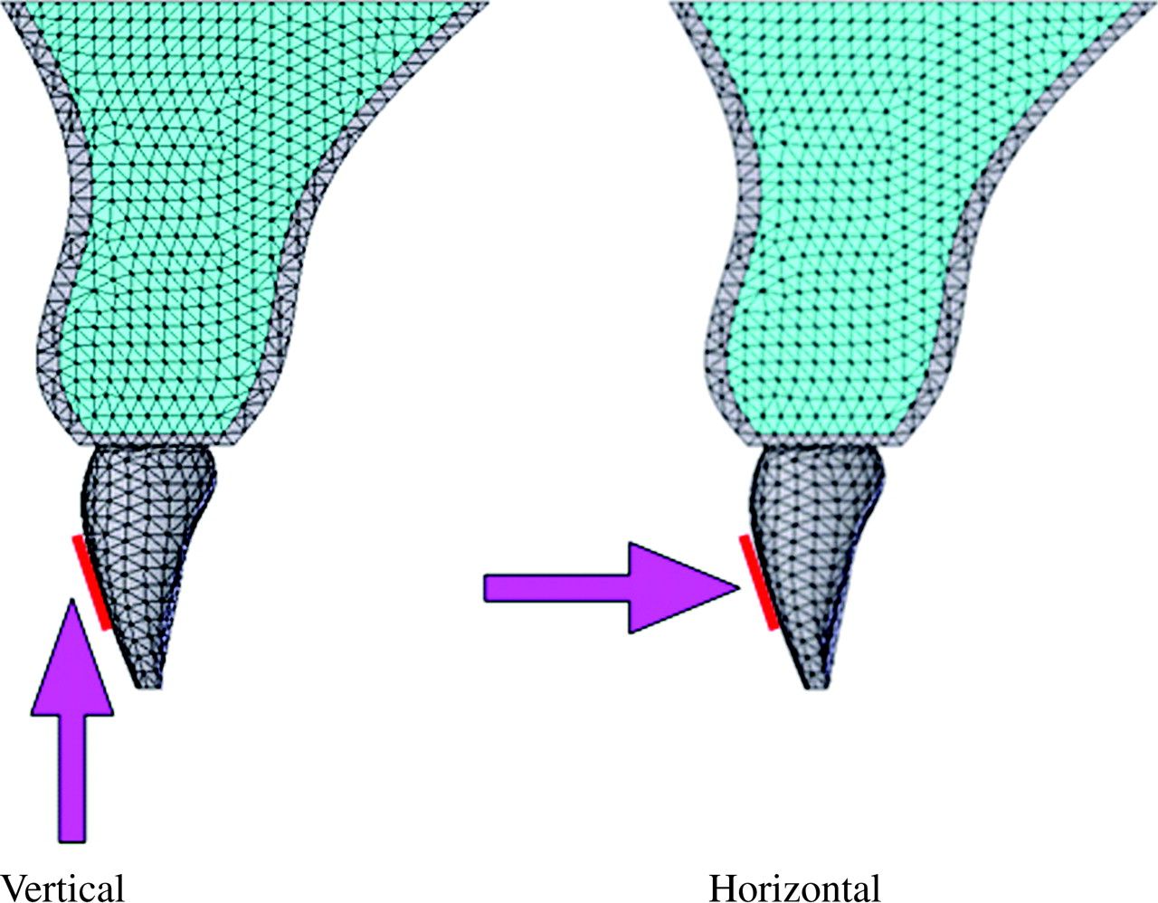
An area of 3.3 × 4.8 mm was fixed as the loaded portion assuming a size reflected by the base of a bracket. Experimental orthodontic forces of 2N in the vertical (intrusive) or horizontal (lingual) direction to the tooth axis were given to the bracket base area (Figure 5).

Loading direction. Distal surface view. An area of 3.3 × 4.8 mm was fixed as the loaded portion assuming a bracket base. Experimental orthodontic forces of 2N in the intrusive or lingual direction to the tooth axis were applied to the bracket base area.
Strains and stresses for each model were calculated using a personal computer (CPU: Celeron® 2.20 GHz, Hard disk: 40.0 GB, RAM: 1024 MB) and the FE program, Cosmos/Works2004 (Cosmos). A linear structural analysis was performed to calculate the stress distribution on the roots.
Results
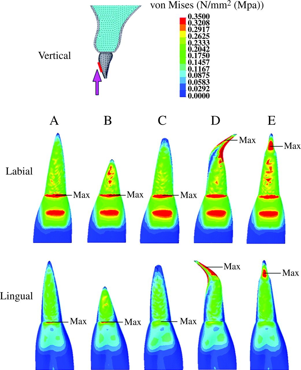
The stress distribution on the central incisor under various conditions is shown in Figures 6 and 7. All models had a tendency to concentrate stress at the cervical area and the bracket base portion of the crown when intrusive force was applied (Figure 6). No significant stress concentration was observed in the root of model A (normal root shape) when intrusive and lingual orthodontic forces were applied (Figures 6 and 7).

Stress distribution on the maxillary central incisor when experimental orthodontic forces were applied in an intrusive direction to the tooth axis. (Labial and lingual surface view.) Red = 0.3 MPa or more; blue = 0.05 or less.

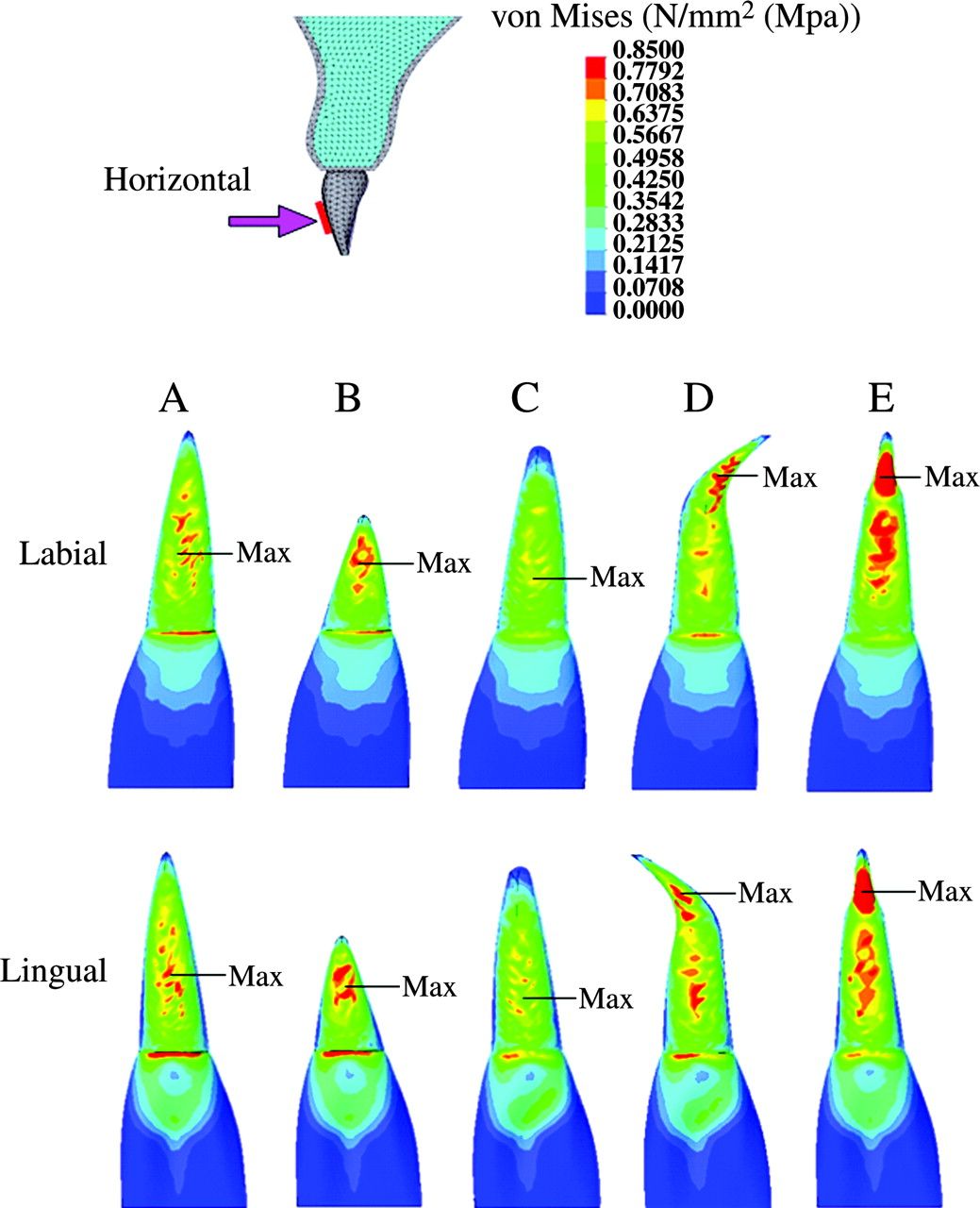
Stress distribution on the maxillary central incisor, when the experimental orthodontic forces were applied in a lingual direction to the tooth axis. (Labial and lingual surface view.) Red = 0.7 MPa or more; blue = 0.1 MPa or less.
In model B (short root), when the experimental orthodontic forces were applied, an area of high-level stress was observed at the middle of the root (intrusive 0.3 MPa or more, Figure 6; lingual 0.7 MPa or more, Figure 7).
Model C (blunt root apex) showed no significant stress concentration in the plot patterns (Figures 6 and 7). When intrusive and lingual forces were applied, the area of high-level stress decreased in model C compared with model A (Figure 6). An area of low-level stress was significantly dominant for model B (intrusive 0.05 MPa or less, Figure 6; lingual 0.1 MPa or less, Figure 7).
During intrusive and lingual force application, model D (bent root apex) showed a significant stress concentration at the mesial and distal portion of the root apex (intrusive 0.3 MPa or more, Figure 6; lingual 0.7 MPa or more, Figure 7).
Model E (pipette shape) showed a stress concentration at the labial and lingual portion in the neck of the pipette-shaped root apex (Figures 6 and 7, respectively).
When intrusive experimental force was applied, a maximum stress value was observed at the cervical area in models A, B, and C, the bent root apex in model D, and the neck of the root apex in model E (Figure 6), while for lingual force, the maximum stress value was at the middle of the root in models A, B, and C, the bent root apex in model D, and the neck of the root apex in model E (Figure 7).
Discussion
In this study, experimental orthodontic force was applied to five FEMs with various root shapes and their stress distribution on the root was evaluated. The forces were applied to the surface, assuming a bracket base, in an intrusive or lingual direction, which are normally used in clinical practice.
When intrusive orthodontic force was applied (Figure 6), for all models (A–E), a higher stress level was observed at the labial than at the lingual surface of the root. This finding could be explained by labial crown torque that would be generated when applying an intrusive force.
For model A, which had a normal root shape, when intrusive and lingual forces were applied, no significant stress concentration was observed at the root apex (Figures 6 and 7).
In model B (short root), significant stress was concentrated at the middle of the root. This finding is related to the alteration of the crown-root ratio. A decrease in the ratio of the root to the crown is thought to enhance loading on the root, resulting in significant stress. Taithongchai et al. (1996) and Thongudomporn and Freer (1998) reported that roots with a short apex enhanced root resorption, which supports the findings of the present study.
Model C (blunt-shaped root) showed no significant stress concentration at the root. The stress level at the root apex was lower than that of model A. The biomechanical burden on the root apex is likely to decrease in blunt-shaped compared with angular-shaped roots. This finding is contrary to the results of Levander and Malmgren (1988) and Thongudomporn and Freer (1998). They reported, in their radiographic studies, that blunt-shaped roots frequently showed root resorption compared with normal roots. The reason for this difference may be related to genetic or other predispositions. Newman (1975) reported that a congenital blunt-shaped root results from physical defects and genetic factors during the root formation stage.
In model D (bent root apex), stress was concentrated at the mesial and distal surface of the root apex during intrusive force application, and at the labial and lingual surface of the root apex when lingual force was applied. The results concerning stress distribution on the bent root shape are in agreement with the findings of Levander and Malmgren (1988) and Mirabella and Årtun (1995) who reported that a bent shape induced root resorption.
For model E (pipette shape), regardless of the direction of force application, stress was concentrated at the neck of the root apex. Sameshima and Sinclair (2001a) and Thongudomporn and Freer (1998) described, in their radiographic studies, that teeth with a pipette-shaped root apex enhanced root resorption. The findings of the present investigation support their results.
The present study clarified stress distribution at the root apex due to various root shapes. In the short, bent, and pipette-shaped roots, stresses were significantly concentrated at the root apex, and therefore, close attention must be paid to deviated root shape.
Kook et al. (2003) reported that teeth with a deviated root shape, i.e. peg-shaped or with short roots, do not always suffer from root resorption. This is thought to be related to risk factors other than mechanical factors. Al-Qawasmi et al. (2003) stated that genetic predisposition influenced external root resorption. McNab et al. (1999) found that asthmatics had significantly more external apical root resorption of the posterior teeth after orthodontic treatment compared with a healthy group. On the other hand, King and Fischlschweiger (1982), in animal experiments, reported that appliances with mean loading of 40 g or less did not significantly increase root resorption, but that stronger forces caused substantial increases in cemental cratering. Chan et al. (2004), in their experimental study, loaded light (25 g) or heavy (225 g) orthodontic forces to the first premolar of humans, and demonstrated that heavy forces caused threefold more resorption than light forces. There is, therefore, a relationship between heavy orthodontic force and external root resorption.
Conclusion
Deviated roots, such as short, bent, or pipette-shaped, resulted in a greater loading of the root than normal root shapes during orthodontic force application. These deviations are suggested to promote root resorption. It is therefore important to identify the root shape at the beginning of orthodontic treatment.

